Basket: £0.00
View Basket »
Open to Trade & Public
Professionals to DIY
Professionals to DIY
CUSTOMER SERVICE
We're Online 9am - 5pm
We're Online 9am - 5pm
FREE DELIVERY
On Orders Over £30
On Orders Over £30
Published: 03/05/2024
All you need to know about Car Batteries
Date Coding of batteries for stock rotation purposes
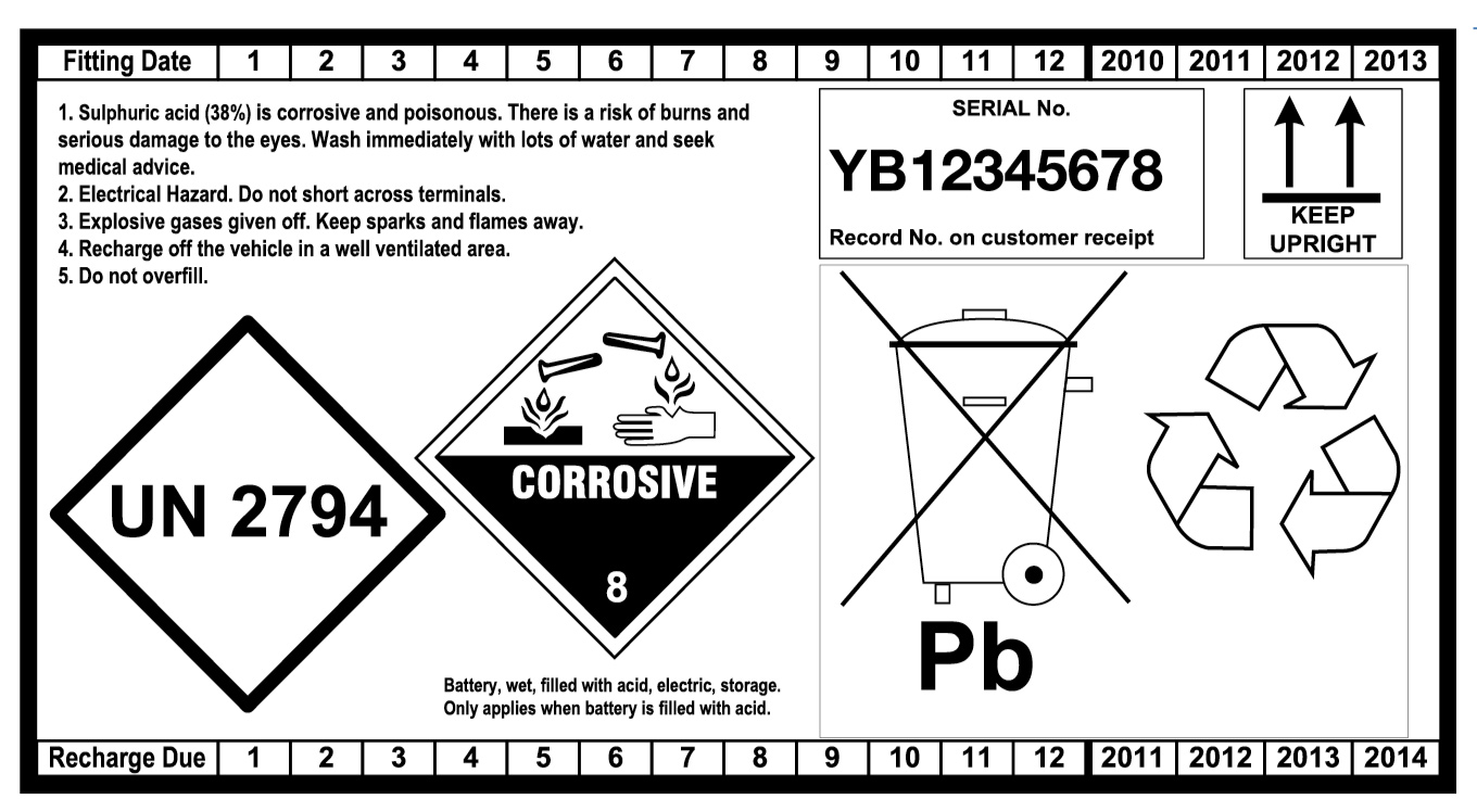
A -Storage
- Always rotate your stock. Practice FIFO (First In, First Out). Batteries slowly lose their charge, and good stock-rotation stops batteries going flat in storage and makes sure that the customer buys a good battery. On the back of the battery there is a label showing the expected period before the battery will require recharging. This makes it easy to identify the oldest and newest batteries in stock. Please use the recharge date to ensure that the oldest batteries leave your stock first. Recharge date is only an indication of recharge period as self discharge is subject to storage conditions.
- Store batteries in a cool, dry, well-ventilated area.
- Protect batteries from excessive heat. (Heat causes batteries to lose charge more quickly, and excessive heat can damage batteries).
- Store batteries in an upright position. (To stop them falling over or leaking).
- Do not stack batteries on top of other batteries. (To avoid scratching, and tearing labels. To avoid damaging terminals that stand proud of the lid).
- Store shrink-wrapped batteries up to 3 high. (Any higher and there is a risk of them falling over and injuring people).
- Do not remove any seals from dry-charged batteries until you are ready to commission the battery by filling it with acid. (The seal preserves the charge in the battery. If it is broken, air will enter and cause the battery to lose charge).
- Store batteries on racks or on pallets, not on the floor. (Small stones or sharp points on a concrete floor can damage the base of the battery and cause leakage).
- Make sure handles are left in the flat (down) position. Upright handles are more likely to be damaged.

B -Maintenance of Stock Handling and Recharging of Batteries
WET Charged Batteries
1. Batteries should be installed ideally within 15 months after manufacture. The voltage should be (worse case higher than 12.25V) ideally higher than 12.4V at the time of installation.
2. Batteries require recharging when the voltage has dropped below 12.4V due to extended warehouse storage. All safety precautions should be undertaken prior to recharging batteries. If a battery has been recharged, the recharge date on the back label should be updated by 6 months after second recharge date by physically notching the label. (Note a maximum of two recharges are allowed prior to sale, and product should not be sold a maximum of 9 months after the expiry of first recommended recharge date).
2.1 A voltage check should be carried out as a matter of course, both to identify older stock and highlight batteries requiring recharge.
2.2 Use a digital voltmeter/multimeter with a minimum of 2 figure resolution (e.g 12.76V).
2.3 Scrap any batteries below 11.0V as these batteries will have developed sulphation that cannot be completed reversed by charging and so will not give the expected performance and life to the customer.
2.4 Note Digital Conductance testers (such as Midtronics and/or Bosch BAT121) are:-
- NOT designed for the testing of new batteries.
- Digital battery testers are not designed to check the fully developed cold cranking performance of a new battery.
- They are designed purely for the testing and evaluation of faulty or used batteries.
- Any CCA/state of health reading from the test on a new battery CANNOT be a reliable guide as to specification of the battery.
See comments on Digital Conductance testers below.
DRY Charged Batteries: Maintenance of Stock
Sales of dry charged batteries within our range is very limited, usually for specialist markets.
- If you keep the batteries cool and dry, and do not remove the seal, dry-charged batteries do not need any other attention.
- The maximum storage time of dry-charged batteries before they are commissioned by filling with acid is 24 months.
- If the seal is damaged, the batteries should be wetted up immediately and the product then treated as WET CHARGED batteries.
- Only commission a dry-charged battery when it is needed for a customer.
- If fitted, remove and discard any sealing plugs, tape or foil.
- If fitted, remove and keep normal vent-plugs and terminal covers (usually red and black).
- For filling, use battery-grade dilute sulphuric acid of specific gravity 1.270 – 1.280 at 25°C conforming to BS3031 or better. (Note: contaminated acid with impurities can seriously damage the life of the battery, in some cases reducing this to a few days. Do not use acid from old batteries).
- The temperature of the acid and the battery should both be at room-temperature in the range 15 – 30°C.
- Fill each cell with acid to a level of 3 – 6mm above the tops of the separators. Fill each cell one after the other and complete the filling in one operation.
- Leave the battery for 20 – 30 minutes and then measure the open-circuit voltage. If it is below 12.50V, charge the battery. If it is above 12.50V, adjust the acid-levels to the correct operating levels with dilute sulphuric acid of specific gravity 1.270 – 1.280. (See Section D below).
- Fit the normal vent-plugs and terminal covers.
- Wash the battery with hot water and dry it.
- Note that performance checks on newly-commissioned dry-charged batteries with modern electronic digital testers using conductance technology are not recommended. Examples are testers supplied by Midtronics or Bosch. The results can be misleading until the battery has undergone some service use.
D -Electrolyte-Levels (Acid-Levels) in Service
Notes: Please read before adjusting acid-levels.
- Do not top up to the maximum levels a battery that needs charging. (Levels rise on charging). However, if the levels are below the tops of the separators, top up with distilled or deionised water until the separators are just covered.
- Adjust levels to the maximum levels only after the battery has stood for at least an hour after charging.
- Never overfill a battery. (The acid may come out of the vent-plugs when the battery is being charged).
- Use only distilled or deionised water for topping up as Sulphuric acid should never be used except for the initial filling of a battery. Do not use bottled Mineral water (impurities within the water will increase water loss and battery self-discharge).
- When the battery is in service, the electrolyte levels should be checked and adjusted to the levels given below.
- If the battery has a maximum level line on the side of the container, fill to this maximum level.
- If there is no maximum line, but there are filling tubes projecting from the bottom of the lid, fill to the bottom of the tubes.
- If there is not a maximum line nor filling tubes in polypropylene batteries, fill to 7mm (0.25 inches) below the bottom edge of the lid-skirt.
- If there are no filling tubes in hard-rubber batteries, fill to 15mm (0.5 inches) above the tops of the separators.
E -Selecting the Correct Battery for the Application
Car and Commercial Vehicle (CV) Batteries
- Select the specified battery from the Yuasa trade Online Vehicle Battery Lookup Tool.
- On 24 Volt systems, or when 2 off 12 Volt batteries are fitted in series, both batteries should be replaced at the same time. Failure to do this will result in a greatly reduced battery life for the new battery that has been fitted. When batteries are joined in series, the negative terminal of one battery is connected to the positive terminal of the other, giving a total voltage of 24 Volts. The Ampere-hour capacity of the system is the same as that of the individual batteries. When batteries are joined in parallel, the positive terminals of the 2 batteries are connected together, and the negative terminals of the 2 batteries are also connected together. The voltage of the system remains unchanged at 12 Volts, but the Ampere-hour capacity of the system is double that of the individual batteries.
Leisure Batteries
- Use the battery with the performance and size recommended by the equipment supplier.
- We recommend that a leisure battery in a medium cyclic application should be sized so that it is not normally discharged to more than 50 per cent state-of-charge. This will ensure that the battery gives a good life. The life of a battery regularly discharged by 50 percent is about 5 times that of a battery regularly discharged to 100 per cent. For example, a load of 4A for 10 hours will discharge a battery by 40Ah. If this represents 50 per cent state-of-charge, we would recommend a 80Ah battery.
Marine Batteries
- The Marine battery range has been designed with greater cyclic durability than the Leisure range and principally designed for hotel load usages on boats.
- The Marine battery range has been designed with sealed lid to exceed the 55° duration requirement according to item 5.10 of EN50342.1 A1 2011.
F -Removing Batteries and Installing Batteries on Vehicles
- It is good practice to tell the customer that, while you will do your best to keep the memory settings, it is possible these might be lost.
- Make sure the hand-brake is on, and that the car is in neutral or park. Switch off all electrical loads and remove the ignition key from the car. Note: On some cars, the doors will lock when the battery is disconnected so this is why the key should be removed from the car. Also switch off any non-factory-fitted alarms.
- Check that the cigar lighter is still working. If not, turn the ignition key to the auxiliary position. Install a Computer Memory Saver (CMS).
- Disconnect the earth-connector first. (This is normally the negative on modern vehicles). This can result in the loss of memory settings; please refer to the vehicle handbook.
- Disconnect the live-connector second. If a CMS is used, the connector will still remain live after it has been disconnected. To prevent the connector shorting against the car, place an insulator such as a rubber glove over the connector.
- Remove the hold-down clamps.
Preparation of a Battery for Fitting
- Check that the battery has the correct polarity for the vehicle.
- Check that the battery has the correct height for the vehicle. (If a battery is too high, it can short out on the bonnet or the bottom of a seat, or it can damage the bonnet).
- It is good practice to place the old and new battery side by side to compare polarities, hold-downs and performance-levels. Some batteries have hold-downs at both the sides and ends. Only the ones used for securing the battery on the vehicle need to be checked.
- Check that the battery is clean and dry.
- Check that the vent-plugs or manifolds are firmly in position.
- Check that the battery has a voltage above 12.40V. If not, charge the battery or use another that has a voltage above 12.40V.
- Ensure the 2 terminal caps are still fitted at this stage.
Preparation of the Vehicle
- Clear away any items on the battery-tray which might damage the battery. (Placing a heavy battery on a piece of sharp grit can puncture the bottom of the battery).
- Check that the connectors, the hold-down clamps and the tray are clean and corrosion-free. (If there is any corrosion, hot water will instantly remove this). If there is severe corrosion which might affect the stability of the battery or has affected other parts of the engine compartment, have the vehicle checked by an authorised distributor.
- Check that the alternator drive-belt tension is correct. Refer to the vehicle handbook or service manual.
- It is recommended that the electrical system, and particularly the charging system, of the vehicle be checked to make sure it is operating correctly. Refer to the vehicle handbook or service manual.
Installing the Battery
- Fit and tighten the hold-down clamps. These should be tight enough to secure the battery and not allow it to move. DO NOT OVERTIGHTEN.
- Connect the live-connector first to the correct battery-terminal (normally the positive) after removing the terminal cap. DO NOT OVERTIGHTEN.
- Connect the earth-connector to the other terminal after removing the terminal cap. DO NOT OVERTIGHTEN.
- Place the 2 terminal caps on the old battery that has been removed from the vehicle to avoid the possibility of short-circuits.
- Replace onto the new battery any components that have been taken from the old battery such as exhaust tubes, vent-elbows, terminal covers, removable hold-down strips (widgets) etc.
- The use of petroleum-jelly (Vaseline) is not necessary on modern polypropylene batteries, but there is no disadvantage in using it. Smear lightly on the terminals. It is still recommended for hard-rubber batteries. Do not use grease.
- Remove the CMS.
- Start the engine
- For non-automotive applications, install the battery in line with the equipment-supplier’s recommendation.
G -Charging Off-Vehicle
Note: Please read before charging batteries
- Do NOT charge a battery if its temperature is below 3°C as the electrolyte may have frozen.
- Charging the battery on the vehicle is not recommended.
- Refer to Section F for information about removing the battery from the vehicle.
- ‘Sealed and AGM’ vehicle batteries should be charged only on constant potential chargers or ‘smart’ chargers. Do not charge on constant current chargers or boost chargers.
- ‘Sealed’ vehicle batteries do not allow any access to the electrolyte, and so cannot be topped up. There are no removable vent-plugs or manifolds. The battery is able to vent gases through breathing holes, and so it is not strictly sealed.
- A new, unused battery with a voltage below 11.00V should be scrapped and not charged. See Section B.
General Procedure for All Types of Chargers
This section gives common information for all types of chargers. The sections below give details for different types of charger.
- 1.Check the electrolyte-levels in all the cells. If these are below the tops of the separators, top up with distilled or deionised water to the tops of the separators. Do not fill to a higher level before charging, but adjust the levels after charging. See Section D.
- If you are using a constant-current charger or a boost-charger, remove the vent-plugs or manifolds before charging. (See below). There is no need to remove the vent-plugs or manifolds if you are using a constant-potential or a ‘smart’ charger.
- Check that the charger is switched off.
- When fitting the charger to the battery, connect the positive lead to the positive terminal and the negative lead to the negative terminal.
- Switch on the charger. See below for the correct charging conditions depending on your type of charger.
- Stop charging if the battery begins to gas freely (some gassing is normal during the last stages of charging) or if the battery temperature rises above 50°C.
- Switch off the charger.
- It is good practice to wait for about 20 minutes for the gases to clear before removing the leads from the battery as some chargers remain ‘live’ and can cause a spark.
- Check the electrolyte-levels in all the cells and top up if necessary. See Section D.
- Refit vent-plugs or manifolds if these have been removed.
- Wash the battery with hot water and dry it.
- Note. Many customers severely underestimate the amount of time necessary to charge a flat battery. This results in customers returning batteries saying that they have charged the battery but that it is still not holding charge.
Types of Charger and How to Use these
There are many types of charger available; their working principles and the procedure for using these is given below.
Index
| Section | Charger Type |
| 1. | Constant Current Chargers |
| 2. | Constant Potential Chargers |
| 3. | Modified Constant Potential Chargers |
| 4. | ‘Smart’ Chargers |
| 5. | Boost Chargers |
1. CONSTANT CURRENT CHARGERS
These maintain a fixed, constant, preset current throughout the charging period irrespective of the battery on-charge voltage. Do not charge AGM batteries on a constant current charger.
Charging Procedure with Constant Current Chargers
A.Ideally, charge each battery on a separate charger unit. If this is not possible, charge batteries in series. We do not recommend charging batteries in parallel because it is not possible to control the amount of current passing through each battery.
If batteries in different states-of-charge are being charged in series, each battery should be removed as soon as it is charged. (If you wait until the last battery is charged, some of the batteries will be overcharged).
B.Measure the open-circuit voltage of the battery. To obtain a stable voltage, the battery should not have been used or charged for a minimum of 3 hours before checking the voltage.
C.Charge the battery at the recommended charge rate (See Battery Specifications section of the Catalogue). If you cannot set the recommended rate, extend or reduce the charging time on a pro rata basis.
For example, if the recommendation is to charge the battery at 4.0A for 6 hours (24Ah = 4.0 x 6), charge the battery for 12 hours if you can only set the charger at 2.0A (24Ah = 2.0 x 12).
D.Charge the battery for the number of hours shown in the table below depending on the open-circuit voltage.
For example, if the battery has a voltage of 12.16V, charge it for 10 hours at the recommended charge rate.
| OPEN-CIRCUIT VOLTAGE (V) | CHARGING TIME (HOURS) |
| Above 12.40 | 4 |
| 12.31 – 12.40 | 6 |
| 12.21 – 12.30 | 8 |
| 12.11 – 12.20 | 10 |
| 12.01 – 12.10 | 12 |
| 11.91 – 12.00 | 14 |
| 11.81 – 11.90 | 16 |
| 11.71 – 11.80 | 18 |
| 11.00 – 11.70 | 20 |
| Below 11.00 | See paragraph E below |
E.If you are charging a battery below 11.00V (overdischarged) that has been in service, a specialised charger capable of providing a very high charging voltage may be necessary, and the recommended current may not be obtainable at first. In this case, monitor the current and adjust as necessary during the charge.
If a battery has become overdischarged, it will have lost both life and performance because of irreversible sulphation. Charging may reduce further its potential life.
2.CONSTANT POTENTIAL CHARGERS
These maintain a fixed, constant, preset voltage throughout the charging period. The current cannot be set and will fall as the battery state-of-charge increases.
Charging Procedure with Constant Potential and Modified Constant Potential Chargers.
A.These chargers are normally designed to charge one battery at a time.
B.Stop charging when the battery is gassing freely and the battery-voltage shows no increase over a period of at least 2 hours.
C.Note. The majority of constant potential chargers are incapable of charging a severely overdischarged (below 11.00V) battery in a realistic period of time. A minimum of
24 hours is normal.
It might be impossible to charge an overdischarged battery.
3.MODIFIED CONSTANT POTENTIAL CHARGERS
The majority of commercial chargers, particularly home-chargers, are of this type, and allow neither the voltage nor the current to be preset.
Charging Procedure with Modified Constant Potential Chargers.
A.Use the same procedure as for Constant Potential Chargers in the paragraph above.
4.‘SMART’ CHARGERS
The latest generation of chargers is able to check the battery condition, and to supply automatically a controlled charge that will charge the battery in the fastest time without damaging it and without overcharging it at the end of the charge. Some ‘smart’ chargers have a special setting for all-calcium batteries and will charge these from flat, which most other chargers are unable to do.
Charging Procedure with ‘Smart’ Chargers
A.Follow the manufacturer’s instructions.
B.These chargers should be able to charge overdischarged (below 11.00V) batteries. Note that some have a special setting for all-calcium batteries.
5.BOOST CHARGERS
These provide a very high initial current, and are used mainly to put some charge into a flat battery when it is needed urgently by the customer. The current falls as the battery state-of-charge increases, and the battery temperature is monitored to make sure it does not overheat.
Charging Procedure with Boost Chargers
A. Boost charging is not recommended except in exceptional circumstances eg a stranded customer, as this will reduce battery life, especially if a battery is boost-charged more
than once.
B.Never boost-charge any battery that is below 11.00 Volts as it will be too sulphated to accept a charge; scrap the battery or charge normally.
C.Only use a boost-charger that limits the charging voltage to a maximum of 14.2 Volts and that has a temperature monitor.
D.Follow carefully the charger-manufacturer’s instructions.
H -Checking Battery Performance
Electronic Testers Using ConductanceTechnology
- The latest generation of testers is digital. Examples are Midtronics and Bosch testers. These will give an immediate decision on about 80 per cent of batteries in service, including flat ones. In the remaining 20 per cent of cases, the batteries need recharging before testing.
- These testers show whether the battery is in a good, charged condition, whether it is discharged or whether it needs replacing.
- Note. This is the preferred method of checking batteries as it does not take any charge out of the battery. It is also easier, quicker and safer.
Digital Conductance Testers Explained
As reported by most battery manufacturers, some confusion has been created within the battery industry regarding the apparent performance of batteries after tests conducted with digital conductance testers (e.g. Midtronics, Bosch BAT121 being the most common types currently on the market).
It is important that the purpose of these tester is clearly understood.
Digital conductance battery testers are not designed to check the cold cranking performance of a new battery.
They are purely designed for testing and evaluation of suspect or used batteries. Any CCA or state of health reading from the test CANNOT be a reliable guide as to the specification of the battery.
The BCI and European EN standard as a testing benchmark for manufacturing process.
Yuasa Batteries (part of the GS Yuasa Corporation) is one of the largest manufacturers worldwide of Lead acid Automotive batteries and its batteries are designed to confirm to the internationally recognised standards.
For example, the initial performance testing procedure according to the EN50342.1 A1 Nov 2011 requires a minimum of 12 working days of testing and significant resources in equipment to validate batteries. All Yuasa branded batteries sold into the market and regularly audit tested to ensure conformance to the relevant standard.
The EN 50342 standard has created further confusion in the market by listed two conformance level standard for high rate cold cranking performance which are not clear to the end user without full access to the ETN part number listing.
EN1 Test @ -18°C 10s to 7.5V, 10 seconds rest than 60% of current to 6V where time should be greater than 73s.
EN2 Test @ -18°C 10s to 7.5V, 10 seconds rest than 60% of current to 6V where time should be greater than 133s.
The rating of the battery obviously varies subject to battery design, but for example a battery rated at 1000A according to EN1, could only be rated at 920A according to EN2. The information of which standard the battery is rated is currently held within the ETN number e.g. 550 034 050<
550=> 12 Volt 50Ah battery
034=> Is a specific number to that battery which gives details of lid type, life, vibration resistance and also whether the battery conforms to EN1 or EN2 high rate
050=> High rate current in this case 500A
There are currently nearly 2000 individual battery numbers listed on the ETN data base by different battery manufacturers and users. This currently makes it unclear to the customer to what rating the battery is capable of meeting EN1 or EN2 without access to the listing.
In order to minimise confusion, Yuasa currently use the longer established American BCI SAE rating for cold cranking amps which is the current to deliver 30 seconds to 7.2V at a temperature of -18°C. This is seen as a fairer comparison to give a balanced view of the batteries durability and starting performance.
The evolution of the Conductance tester into the market
In the last ten years, comparatively inexpensive conductance meters have entered the market which are able to determine the specific internal resistance of an automotive battery using the principles of the AC Wheatstone bridge (which you may remember from school days). The clear advantage of these devices is that they are portable, easily operated, no sparking risks from carrying out traditional high rate load “drop” test and deliver results in just a few seconds.
Disadvantages
The disadvantage of the conductance tester is that they all use a standard algorithm (program) to estimate the CCA reading from the measured internal resistance reading. The values given by these meters are not comparable with those determined using the laboratory test equipment where batteries are physical discharged under real high discharge load, at a temperature of -18°C. Due to differences in battery designs it is not possible to give a perfect relationship between internal resistance and actual performance in the laboratory.
Laboratory testing shows that the algorithm used in conductance testers penalises batteries where the battery design has been optimised (with heavier high density, fine porosity plates) for durability/cyclic endurance than those designs optimised for high rate performance.
For the evaluation of new factory fresh batteries different readings can be seen depending on the manufacturers plate design and acid density. Even significantly different readings can be obtained between different brands of tester. Expanded plates give a higher reading than a cast plate, as the cast plate has a full frame construction for improved conductivity. The grid size can be reduced and made thicker to access the active materials toward the bottom of the plate. This design difference for example has a difference on the conductance readings where the tester correlates to the CCA reading based on a standard formula. The testing of new batteries is more complex as testing under the EN50342 standard requires the battery to be conditioned after a number of cycles which alter the conductance of the paste and hence causes more variation in tester data produced.
For this reason, Yuasa and other major battery manufacturers recommend that the confirmation of the compliance of unused batteries to the EN or BCI can only be determined using laboratory testing and that digital conductance tester are not suitable to evaluate the performance of new unused batteries.
Conductance Tester are designed to measure the internal resistance of the battery. The testers effectiveness on a deeply discharged battery is less effective as although a good starting current figure can be indicated and the vehicle will start, it does not indicate that the 20 hour capacity of the battery may be as low as 10-30%. due to repetitive operation in low states of charge. It is suggested that if this is suspected, the battery should be tested after the lights have been left on for 15 minutes without the engine running.
Open-Circuit Voltage and High-Rate Discharge Testers.
- Measure the open-circuit voltage of the battery using a digital voltmeter or a multimeter. To obtain a stable voltage, the battery should not have been used or charged for a minimum of 3 hours before checking the voltage.
- If the voltage is below 12.40V, charge the battery in accordance with Section G. Note. This type of tester will only give an accurate result on a fully-charged battery. A common mistake is to use this type of tester on a discharged battery, and to judge that the battery is faulty if a cell is seen to ‘boil’. A ‘boiling’ cell on a flat battery does not mean that the battery is faulty.
- Apply a current-load equal to half the SAE CCA cold cranking Amps for 15 seconds. For example, discharge a 600A battery at 300A. Observe the voltage during this time and record the voltage after 15 seconds. You will find the CCA in the Battery Specifications section of the Catalogue or on the label. Use an approved, calibrated tester.
- If the voltage after 15 seconds is stable and above 9.60V, the battery is in a satisfactory condition with no faults.
- If the voltage is below 9.60V after 15 seconds and it is unstable, normally falling quickly, the battery should be replaced.
‘Drop Testers’
- ‘Drop testers’ have 2 spikes that are pressed into the tops of the battery terminals and a simple voltmeter to check the discharge voltage.
- We do not recommend the use of these testers as:
- They are potentially unsafe to use as most types produce a spark when the spikes are first pressed into the terminals.
- The discharge rate is similar for all sizes of battery, and so they do not give a good indication of battery-condition.
- They give misleading results on discharged batteries.
I -Maintenance in Service
General
1 .Always refer to the information contained in the handbook or brochure supplied with the vehicle or equipment.
Definition of Maintenance-Free
- 1.Our starter batteries for cars and commercial vehicles conform to the relevant sections of EN50342.1 A1 Nov 2011 for maintenance-free characteristics. This means that in normal vehicle applications in temperate climate operation, it is not necessary to add water.
- Our batteries are designed to be topped up with water if water should be lost owing to, for example, a charging system fault, prolonged operation in hot climates, excessive off-vehicle charging etc.
- Note. The term maintenance-free applies only when the battery is used in an approved automotive or commercial vehicle application.
Definition of Low Maintenance
- Low maintenance batteries in normal vehicle applications in temperate climate operation need water-addition only at yearly intervals.
- Our batteries are designed to be topped up with water if water should be lost owing to, for example, a charging system fault, prolonged operation in hot climates, excessive off-vehicle charging etc.
- Note. The term low maintenance applies only when the battery is used in an approved commercial vehicle application.
Battery Maintenance in Automotive Applications
- Carry out the checks below at the recommended vehicle service intervals.
- Check the electrolyte-level and top up with water if necessary. See Section D for details about how to do this. (As explained above, it should not be necessary to add water unless the battery has encountered exceptional conditions).
- Check that the battery is clean and dry and that the vents are not obstructed.
- Check that the terminal-connectors and the hold-down clamps are securely-connected and corrosion-free.
- If the battery is on a vehicle that is not to be used for an extended period (more than 1 month), disconnect it from the vehicle. Refer to Section F for information about removing the battery from the vehicle. Modern cars have electrical accessories that slowly discharge the battery even when the ignition key has been removed. Some accessories such as alarms, trackers, and phones can cause a battery to become discharged in a few weeks.
- Fully charge the battery before storage and give it a refreshing charge every 3 months. See Section G.
Battery Maintenance in Non-Automotive Traction and Deep Discharge Applications
- Typical applications are lawnmowers, electric wheelchairs, caravans etc. The Leisure Battery range is recommended for these applications; standard vehicle batteries are not suitable.
- Ensure that the battery is always kept in as high a state-of-charge as possible. Always recharge immediately after use.
- Check the electrolyte-levels on a regular basis dependent upon use. Charging batteries regularly on a non-vehicle charging system may result in a higher rate of water-loss.
- Check that the battery is clean and dry and that the vents are not obstructed.
- If the battery is not to be used for an extended period (more than 1 month), fully charge it before storage, and give it a refreshing charge every 3 months. See Section G.
Battery Maintenance in Non-Automotive Float Applications
- Typical applications are motor-generators, stand-by applications etc. The Leisure Battery range is recommended for these applications; standard vehicle batteries are not suitable.
- Batteries used in these applications should be changed every 2 years or more frequently. (Continuous charging, even from a well-controlled charging system, will result in internal degradation of the battery. This could result in the battery not giving its predicted output when required even though the battery appears to be fully-charged).
- Ensure that the battery is always kept in as high a state-of-charge as possible without causing excessive overcharge. Always recharge immediately after use.
- Check the electrolyte-level on a regular basis dependent upon use, but not less frequently than monthly. Charging batteries continuously on a non-vehicle charging system may result in a higher rate of water-loss.
- Check that the battery is clean and dry and that the vents are not obstructed.
- If the battery is not to be used for an extended period (more than 1 month), fully charge it before storage, and give it a refreshing charge every 3 months. See Section G.
- Best practice is to define a regular maintenance-routine, and to record the results.
- This should include such variables as the amount of water added to each cell, specific gravities in each cell, battery voltage etc.
Use of Battery Additives
- We do not recommend the use of battery additives.
- The use of these invalidates the guarantee.
Click here to purchase Yuasa Batteries - Yuasa Car & Van Batteries
Published: 03/05/2024
AGM & EFB Automotive Batteries Explained
AGM Explained
- Improved active mass efficiency, through better absorption of the acid
- Increased lifespan due to minimal active material shedding due to battery design
- Higher cold start values
- Totally Maintenance Free – zero water consumption
- Spill proof/leak proof
- Designed to meet latest OEM vehicle demands
- Compatible with sensitive electronic equipment
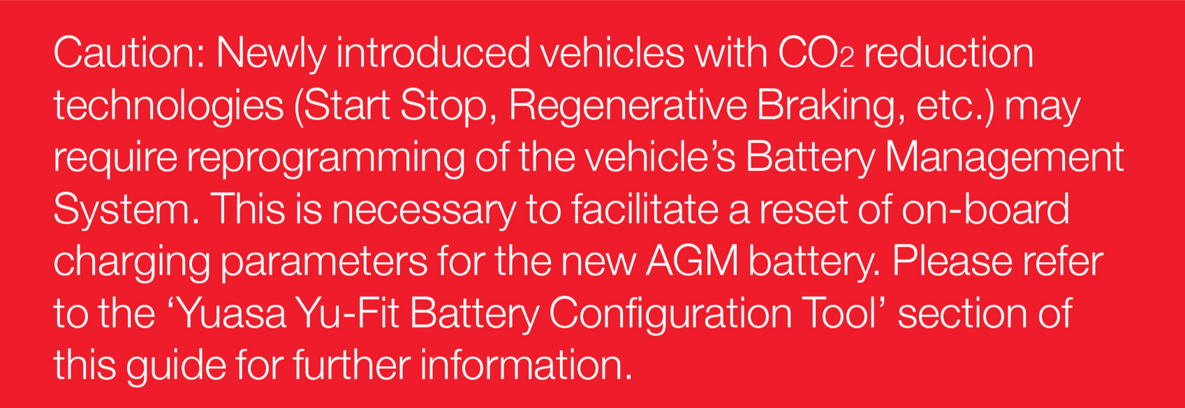
- AGM technology now factory fitted to numerous luxury cars and “Stop – Start” vehicle where increased AGM battery features are required
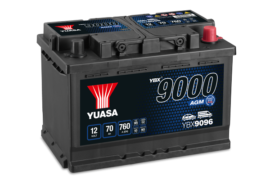
Yuasa’s world leading motorcycle and industrial AGM (absorbent glass mat) technology comes to the automotive market. The Yuasa automotive AGM battery has been engineered to meet the growing extreme power demands of recently introduced vehicles now starting to enter the European aftermarket. Yuasa’s automotive AGM experience comes from vehicles such as the Mazda MX5 and the famous Toyota Prius and has now been launched for European vehicle battery designs.
The new Yuasa AGM European 096 and 019 sized batteries provide reliable starting whilst coping with the extreme power needs of the modern vehicle. Laboratory evaluation is boasting 4-5 times the cyclic durability of standard conventional flooded product and typically 16% higher starting power, even at lower temperatures. Increased reaction surface area ensures increased energy densities for faster engine rotation during starting and therefore maximising fuel efficiency.
The AGM batteries utilises the same absorbent glass mat technology as used in Yuasa Motorcycle and Industrial batteries which have been on the market for over 44 years (1965). This absorbent glass mat absorbs the battery’s acid, enabling a more efficient use of the cell’s volume without the need for electrolyte reservoirs, as needed with conventional flooded batteries. The absorbent glass mat gives a number of key benefits to the design of the lead acid battery:
- Within normal operating conditions, the use of the individual cell valve design and glass mat plate separation ensures gas recombination occurs and ensures that no water is lost therefore negating the need for electrolyte reservoirs and freeing the user from maintenance.
- One way venting system providing partial pressure in each cell ensuring 100% leak proof and safe handling.
- The acid absorption of the glass mat means that the battery packs can be operated under higher pressures than conventional flooded batteries this has benefits including significantly prolonging battery cycle durability by minimising paste shedding.
- The increased pack pressures of the AGM battery increase the batteries resistance to vibration.
- More reaction surface area ensuring higher starting capacity within the same footprint as conventional ?flooded batteries.
Frequently Asked Questions
Q. What are the differences between flooded and AGM Lead Acid batteries?
A. See above, AGM batteries are built using a glass mat separator which enable all the electrolyte required by the battery to be stored within the glass mat, also allowing any gasses given off during charging to be recombined into water meaning that the batteries are totally maintenance free. The design benefits of the glass mat over conventional flooded batteries enable the battery pack to operate under higher pressure without the fear of insufficient electrolyte between the plates, leading to the step change in durability offered by AGM batteries over flooded. The quality of the glass mat is a critical item in ensuring the optimum life of the battery versus its application. This experience has been gained by Yuasa from over 44 years experience in the field using this technology. The automotive application battery designs are balanced with greater high rate starting performance and cycle life for the increased service/technological requirements of modern vehicle designs.
Q. What are the differences between GEL and AGM (starved) batteries?
A. Both are recombinant batteries (i.e. under normal operating conditions they recombine the gases given off during charging to form water) and both are classified as sealed valve regulated.
The major difference is that in the AGM, the electrolyte is fully soaked into a special absorbed glass mat separator which immobilises the acid, whereas in the GEL batteries the acid is mixed with Silica to form a GEL also immobilising the acid. The benefits of AGM over GEL are that with the use of absorbed glass mat, the battery pack can be operated under a greater operating pressure so improving cyclic durability. With GEL, similar pack pressure can not be used so durability is usually provided by increased paste density which is good for life but not as good for high rate startability performance as required for automotive applications.
Q. Why is charging voltage so critical to both GEL and AGM batteries?
A. Charge voltage is critical with these types of batteries as both are recombinant batteries. This means that the oxygen that is normally produced on the positive plate in all lead acid batteries recombines with hydrogen given off by the negative plate. The recombination of the hydrogen and oxygen produces water, which recycles back to the battery acid, therefore the battery is maintenance free and does not need topping up.
The sealing vent used in the design ensures that a positive internal pressure is maintained to ensure the recombination of the gasses occur and not allow the cell ?to dry out and fail.
In addition, the valve must safely release any excess pressure that may be produced during overcharging ?(e.g. alternator rectifier fault), otherwise the cell would be irreversibly damaged. The excessive pressure that the valve is releasing is both hydrogen and oxygen which can not recombined within the battery so breaks the cycle, ?net result is that battery would eventually dry out.
It must be noted that an AGM battery must never be opened once it leaves the factory, as sulphation could occur on the plates leading to an irreversible loss in performance.
Gel batteries are more critical to correct charging as overcharge can lead to the gel being irreversibly damaged, AGM are not subject to this failure mode and hence are more suitable for automotive use.
Q. Can I store my AGM battery in my garage during the winter or will it freeze?
A. As with flooded batteries, providing the batteries are kept ?in a charged state, batteries can be stored without any fears of freezing.
Q. Can I store my AGM battery on the garage floor?
A. Many people have the impression that when batteries sit on concrete the energy “leaks out”, the truth is that you can let any modern battery sit on concrete without fear of harm or accelerated self discharge.
This myth stems from the days of the old wooden/glass case batteries, where damp floors led to water soaking up into outer wooden cases causing swelling of the wood. In fact with modern batteries in hard plastic cases, concrete is generally an excellent surface on which to store a battery. The key issue is that the floor should not have any sharp objects which may damage the battery casing; there are no electrochemical reasons.
Q. Do AGM batteries have a memory?
A. No, this is only a function of Nickel Alkaline Battery system such as Nickel cadmium.
Published: 03/05/2024
Understanding Car Battery Specifications
Yuasa Number
Yuasa battery part numbers are based on the BBMS (British Battery Manufacturers Society) standard which has been used and understood by the UK aftermarket business for many years.
DIN Number 72310 1988
Used to identify battery types, the DIN (German Industrial Standard) Part Number system is traditionally used within Europe, but has now been replaced by ETN number system.
e.g. 560.49
- 1st digit – Voltage
- 1-2 = 6 Volt Battery
- 5-7 = 12 Volt Battery
- 2nd & 3rd digits – Nominal capacity
- 560 = 60Ah @ 20 hour rate
- 660 = 160Ah @ 20 hour rate
- 4th & 5th digits – The unique code number referencing battery performance and features
ETN Number
The ETN (European Type Number) was introduced to replace the DIN Number during Europeanisation of Battery standards. The ETN is a combination of the DIN numbering system which facilitates the changeover and gives further technical details.
The introduction of the ETN system has led to nearly 2000 part numbers being issued during its formal control period up to 2006 and therefore can lead to added confusion if cross referencing of part numbers is required without the formal number index records. The control of number issue by Eurobat was disbanded in 2006 and subsequently issued numbers are now difficult to understand as no formal central records are kept and issued.
The 9-digit ETN offers additional information to the DIN
numbering system.
e.g. 536 046 030
- 1st digit Voltage – 1-2 = 6 volt Battery, 5-7 12 volt Battery
- 2nd and 3rd digits – nominal capacity
- 560 = 60Ah @ 20hour rate
- 660 = 160Ah @ 20hour rate
- 4th, 5th and 6th digits – Unique code number
- 5th and 6th digit can refer sometimes to older battery design and original DIN number (4th and 5th digits)
- The unique code number gives details of endurance level, cold cranking performance level, vibration level, lid, terminal and clamping parts
- 7th, 8th and 9th digits – Cold Cranking Performance
- There are 2 different EN ratings: EN1 and the EN2
- This can cause confusion, as is unclear to the end user which standard is used, especially with the use of digital conductance testers which cannot currently test to both standards.
- Details to which specification the battery is supplied to is hidden within the unique code number.
Cold Cranking Performance (Amps)
The Cold Cranking Performance (CCA) measures the starting performance of the battery. In simple terms, the higher the CCA, the easier it will be to start the vehicle.
SAE (J537 Jun 1994 American Standard)
This is the starting test according to the SAE (Society of Automotive Engineers). The test specifies that the battery at a temperature of –18°C will deliver a current equal to the Cold Cranking Amps for 30 seconds with the voltage staying above 7.2 volts (3.6 volts for a 6 volt battery).
Although subject to battery design, an approximation of SAE to DIN CCA relationship is:- SAE = (DIN x 1.5) + 40.
Battery performance drops off quickly with temperature, so this test is a good check of a battery’s starting ability. With a 10 second voltage of EN rating and its need to support 30 seconds to 7.2V, the SAE test gives a good view of high rate capacity capability of the battery.
DIN (German Industrial Standard at -18°C)
Again, as with SAE, the DIN test is carried out at -18°C. The fully charged battery is discharged to 6V with the rated test current. The voltage must be at least 9.0V after 30 seconds and the time to achieve 6V must be at least 150 seconds.
Although subject to battery design, an approximation of DIN to SAE CCA relationship is:- DIN = (SAE – 40) x 0.66.
Since the introduction of modern fuel injected vehicles and the need for fast starting, the DIN standard has lost favour amongst automotive vehicle manufacturers. Nevertheless, it does show a clear relationship with the amount of materials used within the battery, but not startability.
IEC (International Electro Technical Commission) (IEC 60095-1 Nov 2006)
Again, the IEC test is performed at -18°C . After a rest period of up to 24 hours after preparation (according to 6.2 of standard), the battery is placed in a cooling chamber with air circulation at a temperature of -18°C +/- 1°C until the temperature of the middle cell has reached -18°C +/- 1°C. The battery is then discharged according to the standard and is required to meet a voltage of 7.5V after 10 seconds and 7.2V after 30 seconds. the battery is then rested for 20+/-1 seconds after which the battery is discharged at 60% of the original current and is required to meet a voltage of 6V after 40 seconds, in accordance with table 7 of the standard. The IEC standard has a relationship between the SAE and IEN1 standard and for Yuasa batteries the SAE value can be assumed to equal IEC.
EN (EN50342.1A1 Nov 2011 Item 5.3)
The EN test also is performed at -18°C. The EN requirement is however split into two levels: EN1 and EN2.
EN1 – The battery is required to meet a voltage of 7.5V after
10 seconds; and after 10 seconds rest, the battery is further discharged @ 0.6 x original current and is required to complete 73s in the second stage, giving a total combined discharge period of 90 seconds (assume initial period equates to (10s/0.6)
16.7 seconds.
EN2 – The first discharge is the same as EN1, but the second discharge period to 6.0V should achieve 133 seconds, giving a total time of 150 seconds. The discharge current’s ability to meet both designs is very much subject to battery design and can vary from manufacturer to manufacturer and design to design. However, as an overview of our competitor benchmarking work at Yuasa, the relationship between EN1 and EN2 is:-
EN2 = 0.85% to 0.92% EN1
Due to this relationship, we usually display SAE as our standard to minimise confusion.
JIS (D5301: 1999)
The Japanese Industrial Standard test is carried out at -15°C. The automotive batteries are usually tested at either 150A or 300A with different 10s /30s voltage and durability requirement to 6V. For European applications, we believe this does not give as clear a view to the customer of battery startability and is rarely shown and used within the European aftermarket.
Marine Cranking (MCA)
This Marine cranking test is based on SAE CCA requirement but carried out at the higher temperature of 0°C, usually indicated on batteries as CA (Cranking Amps) or MCA (Marine cranking Amps) rather than CCA (Cold Cranking Amps). The cranking current (CA/MCA) is typically 25% higher than the corresponding SAE CCA marked battery. It is advised that this should be checked with respect to any Marine related cranking current enquires.
The number of automotive battery standards in the world market’s are numerous. Yuasa currently use the SAE CCA standard as a norm, giving a clear, balanced representation of battery cranking performance between startability and starting endurance.
According to EU1103: 2010 Capacity Marking Directive, Yuasa use capacity (20 hour) and EN1 CCA as specified in standard EN50342.1 A1 2011. Please note, due to algorithm issues in existing impedance testers on the market, all testing on Yuasa batteries should follow the old SAE algorithm (not EN or IEC as ranges are still specified against obsolete versions of the standard).
Reserve Capacity Minutes (EN50342.1 A1 Nov 2011 Item 5.2)
The Reserve Capacity is the amount of time in minutes that a battery at 25°C can deliver a current of 25 Amps until the voltage drops to 10.50V (5.25V for a 6-volt battery).
25 Amps represents a typical electrical load on a car under normal running conditions, so the Reserve Capacity gives an indication of the time that a vehicle with a normal electrical load will run with a broken alternator or fan-belt. This is a good, practical test.
Obviously, the more electrical accessories you turn off, the further you can drive the car.
Reserve Capacity was originally used to give an indication of the capacity of the battery if the then charging system (dynamo) failed and the duration of driving time left after charging warning light first appeared. With the greater dependability of modern vehicle charging systems the direct usefulness of reserve capacity to the automotive user has dropped, but does show the relative drop off in battery performance as the discharge current is increased.
Ampere-Hour Capacity at 20 Hour Rate (Ah) (EN50342.1 A1 Nov 2011 Item 5.1)
The Ampere-Hour Capacity measures the total amount of electricity stored in a battery.
An Ampere-Hour represents the amount of electricity when a current of 1 Ampere passes for 1 hour.
The Ampere-Hour Capacity varies with the rate at which the battery is discharged; the slower the discharge, the greater the amount of electricity that the battery will deliver.
The Ampere-Hour Capacity is the amount of electricity that a battery will deliver during 20 hours before the voltage falls to 10.50V. For example, a 60Ah battery will deliver a current of 3A for 20 hours.
Recommended Charge Rate (Amps)
This is the recommended current for charging batteries with a constant-current charger.
For more details, see Section G of ‘All You Need To Know About Batteries’.
Dimensions – Length (mm)
This is the dimension over the longest part of the battery, including the hold-down if fitted.
Dimensions – Width (mm)
This is the dimension over the widest part of the battery, including the hold-down if fitted.
Dimensions – Height (mm)
This is the overall height of the battery to the tops of the terminals if these are proud of the lid.
Weight with Acid (kg)
This is the average weight of the battery as supplied.
Cell Layout
Cell layout and polarity diagrams can be found in the ‘diagrams’ tab on each Yuasa battery product page. Alternatively, the battery’s datasheet can be downloaded.
Terminal
Information about the type of terminal fitted to the battery can be found in the ‘technical specification’ tab as well as the ‘diagrams’ tab.
Container Features
Again, information about container hold-downs and other features can be found in the ‘diagrams tab’ on each Yuasa battery product page.
Handles
Information about whether the battery is fitted with carrying handles can also be found in the ‘technical specification’ tab.
End-Venting
There are now several batteries in the range that have end-venting, rather than the normal venting through the individual vent-plugs.
Information about whether the battery is fitted with end-venting at the negative end can be found in the ‘technical specification’ tab.
The battery is fitted with a gassing outlet according to EN60095-2 + EN50342.2 2007 item 5.5.3 and Figure 10 to allow remote venting of the battery.
State of Charge Indicator
A clever floating ball and prism device fitted to one cell of the battery to give a quick visual guide to battery state of charge and electrolyte level within the battery. If concerns are noted, it should be used as advice to seek further engineering support.
Lid Features
An indication of lid design feature which may be specific to vehicle fitment:-
- Block – T shaped lid feature to give recessed area for terminals, and for European types this is sufficient for top clamping according to IEC 60095-2 and EN50342.2 007 item 5.5.1.
- Flat – Flat lid feature with no raised plugs which could interfere with manufacturers top clamp frame.
- Raised plugs – Raised vent plug design sitting above the top face of the lid.
Semi-Traction Features
These make the battery suitable for applications in which there is some cycling (e.g. vehicles with tail-lifts).
GS Yuasa Automotive Online Battery Look Up Tool
GS Yuasa endeavour to incorporate the most up to date and accurate information into the online battery look up tool. We gather the OE data and compare this information against the batteries in our range. We then output a match between original battery fitted by the vehicle manufacturer and the GS Yuasa battery range.
Inevitably there might be marginal differences in CCA and Ah between what was originally fitted and the battery in our range. The very small differences involved will not have a detrimental effect to the electrical system within the vehicle.
Notes
Throughout the life of any Lead Acid vehicle battery the capacity will slowly reduce due to aging effects and usage. At the end of battery life, the lack of capacity and subsequent drop in voltage may cause electrical error codes. When a new battery is fitted any error codes caused by the old battery could remain. When the vehicle is then presented to a garage, an assumption might be made that the new battery has caused the problem. Small variances in Ah between OE and aftermarket batteries will not cause electrical problems of this nature.
Battery standards such as EN50342.1, allow for variances in actual Ah and the label rating, to account for variances in manufacturing. These differences will be evident in OE batteries as with any after market battery.
Click here to purchase Yuasa Batteries - Yuasa Car & Van Batteries
Published: 03/05/2024
Auxiliary & Back-up Automotive Batteries Explained
Auxiliary Battery Overview
Modern vehicles with CO2 reduction technologies, high levels of specification, and new electronic driver aids may feature an auxiliary battery alongside the main vehicle starter battery or high voltage system battery on Hybrid and electric vehicles. Auxiliary batteries vary in size and specification dependent on the demands placed on it by the vehicle electrical system and can be used as a safety back-up to support the main battery when required or to provide voltage for specific vehicle systems all of the time.
IC Dual Battery Systems
The dual battery system isolates all power supply sensitive electrical components which may be affected by low voltage from the primary battery during the engine starting phase.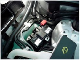
Two contact switches are used to change the power supply into two separate circuits when an engine start is required.
Electrical power is then supplied to the sensitive electrical components from the secondary battery when an engine start is in progress.
The primary battery supplies power to the starter motor and maintains essential power to the Engine Management System (EMS) which is essential for engine starting.
Primary and secondary battery voltages are monitored to ensure sufficient voltage is available for the next start event and charge can be supplied to the secondary battery when required.
IC Dual Battery System Components
System components:
1. Starter motor
2. Primary battery
3. Power & EMS loads
4. Field effect transistor
5. Contact switch 1
6. Contact switch 2
7. Secondary battery
8. Sensitive loads
9. Alternator
IC Dual Battery System Operation
System Conditions – Start Required
• Contact 1 open
• Contact 2 closed
The primary battey supplies the starter motor and the secondary battery supports power supply sensitive components
System Conditions – Engine Running
• Contact 1 closed
• Contact 2 open
The primary battery is being charged by the alternator and the secondary battery is isolated from the circuit.
If the system detects a low auxiliary battery voltage contact 2 will remain closed once the engine is running to enable the auxiliary battery to be fully charged by the alternator.
Once the auxiliary battery is fully charged contact 2 will open to prevent damage to the axuiliary battery and reduce alternator and consequently engine loads to save fuel and reduce emissions.
Hybrid Vehicle Auxiliary Battery
 Most Hybrid vehicles such as the Toyota Prius feature a conventional 12 Volt auxiliary battery in addition to the high voltage hybrid system battery.
The 12 Volt battery is not used for engine starting or to power the traction motors but is used to supply power to:
- Accessory systems
- Headlights
- Audio systems
- Computer controls
Electric Vehicle Auxiliary Battery
 Electric vehicles such as the Mitsubishi i-miev feature a conventional 12 Volt auxiliary battery in addition to the high voltage traction battery.
The auxiliary battery is not used by the traction motor but is charged by the traction battery and is used to support all of the electrical systems on the vehicle with the exception of:
- Air conditioning
- Heating system
Click Here to purchase Yuasa Auxiliary Batteries - Yuasa Auxiliary Batteries
Published: 03/05/2024
AGM vs. EFB Car Batteries: Choosing the Right Power Source | Blog

Introduction: Car batteries are the heartbeat of your vehicle, providing the necessary power to start the engine and operate various electrical components. As automotive technology advances, so do the types of batteries available on the market. Among the newer options are Absorbent Glass Mat (AGM) and Enhanced Flooded Battery (EFB) technologies, designed to offer improved performance and reliability. In this blog post, we'll delve into the differences between AGM and EFB car batteries to help you make an informed decision when choosing the right power source for your vehicle.
What are AGM and EFB Batteries? AGM and EFB batteries are both types of lead-acid batteries, commonly used in modern vehicles, especially those equipped with start-stop systems and other advanced electrical features. While they share some similarities, such as their basic composition and function, there are distinct differences in their design and performance characteristics.
Absorbent Glass Mat (AGM) Batteries: AGM batteries are constructed with a unique design that incorporates absorbent glass mats sandwiched between the battery's plates. These mats are saturated with electrolyte, allowing for better retention and distribution of the acid solution. This design feature enhances the battery's durability and resistance to vibration, making AGM batteries ideal for vehicles with demanding electrical requirements.
Key Features of AGM Batteries:
- Enhanced Durability: AGM batteries are highly resistant to vibration and shock, making them suitable for rough driving conditions.
- Maintenance-Free: Unlike traditional flooded batteries, AGM batteries are sealed, eliminating the need for electrolyte maintenance.
- Faster Recharge: AGM batteries have lower internal resistance, allowing for quicker charging and higher output currents.
- Deep Cycle Capabilities: AGM batteries can withstand deeper discharges without suffering damage, making them suitable for vehicles with frequent start-stop cycles.
Choosing the Right Battery for Your Vehicle: When selecting a battery for your vehicle, it's essential to consider your specific driving habits, vehicle requirements, and budget constraints. Here are some factors to keep in mind:
- Vehicle Compatibility: Consult your vehicle manufacturer's recommendations to determine whether AGM or EFB batteries are compatible with your vehicle's electrical system.
- Performance Requirements: If your vehicle features advanced electrical systems or frequently undergoes start-stop operation, AGM batteries may offer superior performance and longevity.
- Budget Considerations: While AGM batteries typically command a higher price point than EFB batteries, they may provide better long-term value due to their durability and maintenance-free operation.
- Environmental Conditions: Consider factors such as temperature extremes and driving conditions when selecting a battery type, as these factors can impact battery performance and lifespan.
Our Branches
York Tel: 01904 628828
Malton Tel: 01653 602700
Selby Tel: 01757 403300
Scarborough Tel: 01723 413104
Poppleton Tel: 01904 917280
Harrogate Tel: 01423 223940
Thirsk Tel: 01845 421421


© Copyright 2019 York Motor Factors ~ Head Office: 62 Layerthorpe, York. YO31 7YW ~ Reg number 0955941 Vat reg number 170164586